

I’m making mechatronic Dr Octopus arms (they’re gonna be pretty sweet), and I’m in the process of prototyping the segments. They’ll be roughly 2.5 cm in height, with a 2.5 cm gap from segment to segment, and they need to be attached securely, with smooth rotation on xyz to ≈ 10°. Planning on housing the servos in the base, and running cables down the arms to actuate them. Roughly 24 segments total, with separate control cables for the first 12 and second 12 (so the first half can bend in one direction, and the second half another), along with a drive cable down the center so it can rotate on the z axis. This also means I’ll need some empty space running down the center of the segments to run the drive cable and the control cables for the second half, so they don’t impede/aren’t impacted by the bending of the first half.
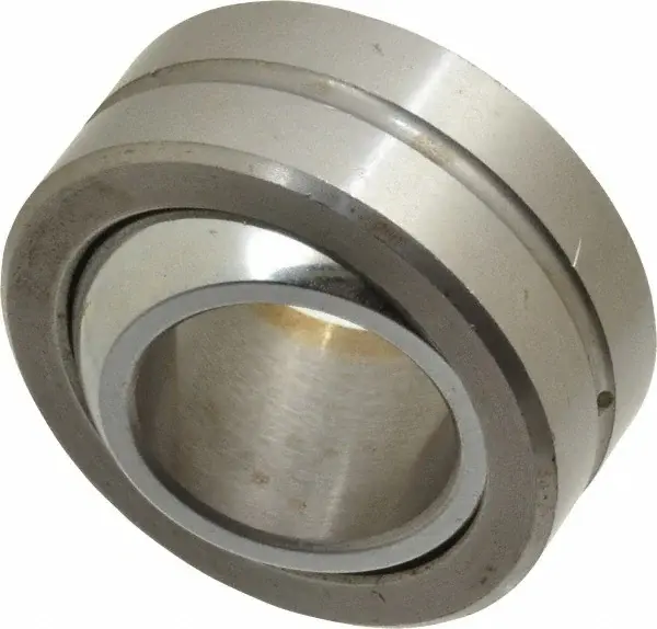
As far as I can figure, spherical bearings are my only real option here. As a test, I bought 4 steel spherical bearings from Amazon to connect the segments. And man, I love these things. I’d never handled them before, and they are smooth as butter. Unfortunately, they were like $7/per, and I need around 100 of them. So, slightly more than I’m hoping to spend haha. Aliexpress has them for ≈ $1.50/per, but the shipping is obscenely expensive, and would take like 2 months.
So I’m trying to figure out another option. I’m a member of a local maker’s space, so I have access to a bunch of tools (metal shop with lathe, CNC, FDM 3D printers), but still don’t think I have a great solution.
The tools for making these the right way are obscenely expensive. I’m thinking I could machine the race in two halves and weld/clamp them around the ball, which would be a ton of work, and wouldn’t be as smooth, but would probably be sufficient.
I could 3D print them, but I can’t figure out a process that would be as smooth as I want. They’d need to be filled/sanded, probably coated with a dry lubricant. But the filling/sanding process would introduce tolerance issues, and I can’t afford to have slop with how the cables will work.
Anyone have any insights here to help me out? Thanks!
In a complete change of direction, might it be possible to model the joints as a “bendy straw” joint and avoid this whole question of bearings?
Sure it’s possible, in fact I’m running several PTFE tubes through the center of the joints (for the drive cables and control cables) that effectively function like that. My biggest concern with this whole thing is how much it’s going to bounce around while I’m walking. I feel like a “bendy straw” will be too susceptible to shear/compression forces to give the rigidity I’m looking for.
And a hinge of some sort between the two tubes wouldn’t do it for you? You want more than one plane of movement for each segment, is it?
Yes, the joint needs to rotate on x, y, and z to about 10 degrees